Raw material quality control in CNC machining ensures that only high-quality materials are utilized in manufacturing. By systematically inspecting and verifying the quality of these materials, manufacturers can assess their composition, mechanical properties, and adherence to industry standards. In this article, we’ll talk about the key material properties to inspect in quality control and how they are inspected.
What Is Raw Material Quality Control in CNC Machining?
Raw material quality control in CNC machining involves systematically inspecting and verifying the quality of materials before they are used in manufacturing processes. This includes assessing the composition, mechanical properties, and compliance with industry standards to ensure that materials meet the necessary specifications for their intended applications. The importance of this control lies in its ability to ensure product quality, minimize waste and costs, maintain production efficiency, enhance customer satisfaction, and comply with regulatory standards, ultimately leading to reliable and high-performing components.
Raw Material Properties Quality Inspection/Testing Methods, Tools and Steps
When inspecting raw materials for CNC machining, several key parameters are critical.
Material Dimensions Inspection
Accurate measurements are crucial to ensure that raw materials fit within design tolerances. This involves the use of precise tools such as calipers and coordinate measuring machines (CMM) to confirm that dimensions align with specifications.
Measurement Tools
- Calipers: Such as vernier calipers, dial calipers, and digital calipers. Used for measuring internal, external, and depth dimensions. They are versatile and suitable for a wide range of machining tasks.
- Micrometers: Outside micrometers, inside micrometers, thread micrometers, and depth micrometers. Ideal for high-precision measurements of thickness, diameter, and depth. They provide accuracy in the range of micrometers or millimeters.
- Height Gauges: Used to measure the height, steps, and depth of machined components. They are particularly useful for inspecting large objects.
- Coordinate Measuring Machines (CMM): These devices use probes or laser beams to measure the coordinates of points on a part’s surface. They provide three-dimensional measurements and are essential for inspecting complex parts.
- Profile Projectors: These optical measuring instruments are used to inspect the outlines of workpieces. They project the shadow of the part onto a screen for precise measurement and are ideal for non-contact measurements.
- Optical Comparators: These tools use optical magnification to compare the dimensions of a part to a reference. They are useful for quick, non-contact measurements of simple geometries.
- Laser Scanners: Laser scanners use laser beams to capture the shape and geometry of a part. They generate a three-dimensional representation of the part and are commonly used for reverse engineering and quality control.
- Thread Gauges: Used for measuring the pitch and diameter of threaded components. These tools ensure proper thread engagement and quality control.
- Go/No-Go Gauges: These are specialized tools used to check if a part falls within a specific tolerance range. They perform pass/fail tests and are ideal for quick inspections.
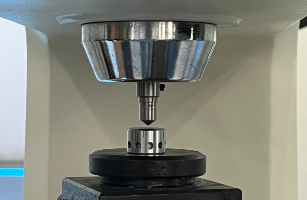
Material Hardness Testing
This property indicates the material’s resistance to deformation and is assessed through various testing methods, including Rockwell, Brinell, and Vickers tests. Each method determines hardness differently, suitable for various material types.
1. Brinell Hardness Test
The Brinell hardness test involves pressing a steel or carbide ball into the material under a specific force and measuring the diameter of the indentation created. This method is advantageous because it provides an average hardness value over a larger area, making it less sensitive to surface irregularities. It is particularly suitable for testing metals, alloys, castings, and coarse-grained materials.
Tools/Equipment:
- Brinell Hardness Tester
- Indenter (steel or carbide ball)
- Sample Holder
Procedure:
- Sample Preparation: Ensure the material surface is flat, smooth, and free of contaminants.
- Positioning: Place the material on the sample holder and align it under the indenter.
- Applying Load: Select the appropriate load and apply it for 10-15 seconds.
- Measuring Indentation: Measure the diameter of the indentation using a microscope.
- Calculating BHN
2. Rockwell Hardness Test
The Rockwell hardness test measures the depth of penetration of an indenter (either a diamond cone or steel ball) under a major load compared to a preload. Its key advantage is its speed and simplicity, providing immediate hardness readings without complex calculations. The test can be applied to a wide range of metals, including steel, aluminum, and brass.
Tools/Equipment:
- Rockwell Hardness Tester
- Indenter (diamond cone or steel ball)
- Support Anvil
Procedure:
- Sample Preparation: Ensure the surface is clean and flat.
- Positioning: Place the material on the support anvil and align it under the indenter.
- Applying Preload: Apply a minor preload to seat the indenter.
- Applying Major Load: Apply the major load for a specified dwell time, then release it while maintaining the preload.
- Reading Result: Read the hardness value directly from the display.
3. Vickers Hardness Test
The Vickers hardness test involves pressing a diamond pyramid indenter into the material and measuring the diagonal length of the resulting indentation. This method offers precise and consistent measurements, making it ideal for quality control and research purposes. It is versatile, suitable for various materials from soft to hard, including small parts and coatings.
Tools/Equipment:
- Vickers Hardness Tester
- Diamond Indenter
- Sample Stage
Procedure:
- Sample Preparation: Polish the material surface to minimize measurement errors.
- Positioning: Secure the material on the sample stage and align it under the indenter.
- Applying Load: Select the appropriate load and apply it for the specified dwell time.
- Measuring Indentation: Measure the diagonal length of the indentation using an optical system.
- Calculating HV: Use the formula HV=d²/1.8544P
4. Shore Hardness Test (for Polymers and Rubbers)
The Shore hardness test measures the indentation created by a spring-loaded indenter. Its simplicity and quick execution allow for immediate hardness readings, making it effective for evaluating polymers, elastomers, and rubbers. This test is widely used in industries requiring rapid assessments of material softness and hardness.
Tools/Equipment:
- Durometer
- Sample Holder
Procedure:
- Sample Preparation: Ensure the material surface is flat and free of defects.
- Positioning: Place the material on the sample holder and position the durometer on the surface.
- Applying Pressure: Apply pressure until the indenter is fully depressed.
- Reading Result: Read the Shore hardness value directly from the durometer’s scale after a specified dwell time.
Material Strength Testing
The material’s ability to withstand force without deformation is evaluated through tensile, compressive, and shear tests. These tests help ensure that materials can handle expected operational loads without failure.
1. Tensile Testing
Tensile testing evaluates a material’s properties under tensile forces by applying a controlled load to a dogbone-shaped specimen until it fractures. This method provides comprehensive data on mechanical properties, aiding in material selection for specific applications, and is vital for quality control, research and development, and designing structural components.
Tools/Equipment:
- Tensile Testing Machine: Equipped with a loading mechanism, displacement sensor, and data acquisition system.
- Dogbone-shaped Specimen: Prepared sample with a reduced cross-section for fracture focus.
- Grips: Secure the specimen during testing.
- Extensometer: Measures elongation to determine strain.
Procedure:
- Prepare a dogbone-shaped specimen with precise dimensions.
- Secure the specimen in the grips of the tensile testing machine.
- Gradually apply load until fracture occurs.
- Continuously record load and displacement.
- Calculate properties like ultimate tensile strength and modulus of elasticity.
2. Compression Testing
Compression testing assesses a material’s compressive strength by applying force to flatten or crush it. This method is crucial for understanding how materials behave under compressive loads, making it essential for quality control in construction materials and packaging applications.
Tools/Equipment:
- Compression Testing Machine: Designed to apply compressive forces.
- Test Specimen: Cylindrical or cubic sample of the material.
- Loading Plates: Ensure uniform force application.
Procedure:
- Prepare a cylindrical or cubic specimen.
- Place the specimen between the loading plates.
- Gradually apply compressive load.
- Record load and displacement data.
- Calculate compressive strength and elastic modulus.
3. Bend Testing
Bend testing evaluates a material’s ductility and fracture resistance by applying a bending force. This test is important for determining a material’s suitability for applications involving bending forces, offering insights into its behavior and guiding material selection for metal forming and construction uses.
Tools/Equipment:
- Bend Testing Machine: Applies bending forces to the material.
- Test Specimen: Rectangular or cylindrical sample.
- Support and Punch: Support the specimen and apply force.
Procedure:
- Prepare a specimen with specified dimensions.
- Place the specimen on the supports.
- Apply force using the punch.
- Observe and record material behavior during bending.
- Calculate bend strength and ductility.
4. Impact Testing
Impact testing measures the energy required to fracture a material under sudden impact, thus evaluating its toughness and resistance to brittle fracture. This method is crucial for ensuring material reliability in aerospace, automotive, and safety applications.
Tools/Equipment:
- Impact Testing Machine: Delivers sudden impact force.
- Test Specimen: Notched or unnotched sample of the material.
- Pendulum Hammer: Delivers the impact.
Procedure:
- Prepare the specimen with or without a notch based on requirements.
- Secure the specimen in the impact testing machine.
- Release the pendulum hammer to strike the specimen.
- Measure the energy absorbed during fracture.
- Calculate impact strength or toughness.
5. Fatigue Testing
Fatigue testing assesses a material’s ability to endure cyclic loading over time, determining its fatigue strength and endurance limit. This test is vital for quality control in sectors like aerospace and automotive, where materials are subjected to repeated stress cycles.
Tools/Equipment:
- Fatigue Testing Machine: Applies cyclic loads.
- Test Specimen: Sample with specified dimensions.
- Loading System: Applies cyclic load.
- Data Acquisition System: Records cycles, load, and displacement.
Procedure:
- Prepare a specimen with precise dimensions.
- Secure the specimen in the fatigue testing machine.
- Apply a cyclic load for a specified number of cycles.
- Continuously record load, displacement, and cycles.
- Determine fatigue strength and endurance limit.
6. Torsion Testing
Torsion testing measures a material’s properties under twisting forces, evaluating shear strength and modulus of rigidity. This method is crucial for applications involving torsional loads, guiding material selection for components such as shafts in mechanical engineering.
Tools/Equipment:
- Torsion Testing Machine: Applies torsional forces.
- Test Specimen: Cylindrical or rod-shaped sample.
- Torque Measurement System: Measures applied torque and angular displacement.
Procedure:
- Prepare a cylindrical or rod-shaped specimen.
- Secure the specimen in the torsion testing machine.
- Gradually apply torque.
- Record torque and angular displacement.
- Calculate shear strength and modulus of rigidity.
Surface Roughness Measurement
The texture and finish of the material’s surface are assessed through visual inspection and surface roughness measurement. A smooth surface is often necessary for high-performance components, and roughness is quantified using specialized tools.
1. Contact Profilometers
Contact profilometers operate by using a diamond stylus that slides across the surface of a machined part, capturing its deflections to assess surface roughness. This method is known for its high precision and versatility across various surfaces. However, it may damage delicate materials and can be time-consuming.
Tools/Equipment:
- Diamond Stylus: A highly sensitive probe that traverses the surface.
- Measurement Device: Records the vertical deviations of the stylus.
- Display Unit: Displays the measured roughness values (e.g., Ra, Rz).
Procedure:
- Sample Preparation: Ensure the surface is clean and free of contaminants.
- Positioning: Secure the part on the measurement device.
- Measurement: Move the stylus across the surface at a controlled speed.
- Data Analysis: The device calculates and displays the surface roughness values.
2. Non-Contact Profilometers
Non-contact profilometers utilize technologies such as laser triangulation or confocal microscopy to measure surface roughness without physical contact. This approach is advantageous because it is fast and non-destructive, making it ideal for delicate or reflective surfaces. However, it tends to be more expensive and complex than contact methods.
Tools/Equipment:
- Laser Source: Emits a beam of light onto the surface.
- Sensors: Capture the reflected light to create a surface profile.
- Data Processing Unit: Analyzes the data to determine roughness values.
Procedure:
- Sample Preparation: Ensure the surface is clean and free of contaminants.
- Positioning: Place the part under the laser or optical system.
- Measurement: The laser or optical system scans the surface.
- Data Analysis: The system processes the data and displays the roughness values.
3. Atomic Force Microscopy (AFM)
Atomic Force Microscopy employs a sharp probe to scan surfaces at the atomic level, delivering nanometer-level accuracy in surface measurements. Its exceptional resolution allows for the assessment of magnetic and mechanical properties, though it is costly and time-intensive, making it best suited for research and high-precision applications.
Tools/Equipment:
- Probe: A sharp tip mounted on a cantilever.
- Scanning System: Moves the probe across the surface.
- Data Acquisition System: Records the interactions between the probe and the surface.
Procedure:
- Sample Preparation: Ensure the surface is extremely clean and flat.
- Positioning: Secure the sample on the scanning stage.
- Measurement: The probe scans the surface, and the cantilever records surface irregularities.
- Data Analysis: The system generates a 3D map of the surface and calculates roughness values.
4. 3D Scanning
3D scanning generates a detailed topographical map of a surface, enabling comprehensive roughness analysis. This method offers a holistic view of surface structure and roughness, but it requires sophisticated equipment and expertise, making it less accessible for general use.
Tools/Equipment:
- 3D Scanner: Uses advanced optical or laser systems.
- Software: Processes the scanned data to create a 3D model.
Procedure:
- Sample Preparation: Ensure the surface is clean and free of contaminants.
- Scanning: Use the 3D scanner to capture the surface topography.
- Data Analysis: The software analyzes the data to determine roughness parameters.
Surface Defects Inspection
1. Visual Inspection
Visual inspection involves inspectors examining surfaces for defects such as scratches, dents, and discoloration. This method is simple and cost-effective, making it accessible for many applications. However, it is subjective and can lead to the oversight of subtle defects that may not be easily visible.
Tools/Equipment:
- Magnifying Glasses: For closer inspection.
- Lighting: Proper lighting to highlight surface irregularities.
Procedure:
- Sample Preparation: Ensure the surface is clean.
- Inspection: Use magnifying tools and lighting to examine the surface.
- Documentation: Record any observed defects.
2. Optical Metrology Systems
Optical metrology systems utilize advanced optical techniques to detect surface defects, capturing high-resolution images for detailed analysis. This approach offers high accuracy and speed, making it suitable for automated inspection. However, it requires specialized equipment and expertise, which can be a barrier to implementation.
Tools/Equipment:
- Optical Sensors: Capture high-resolution images of the surface.
- Image Processing Software: Analyzes the images for defects.
Procedure:
- Sample Preparation: Ensure the surface is clean.
- Imaging: Capture images of the surface using optical sensors.
- Analysis: The software identifies and classifies defects.
3. Machine Vision Systems
Machine vision systems employ cameras and computer vision algorithms to identify surface defects on various parts. This method is automated, fast, and reliable, enhancing inspection efficiency. However, it often involves high initial costs and requires calibration to ensure accuracy and effectiveness.
Tools/Equipment:
- Cameras: High-resolution cameras to capture surface images.
- Lighting Systems: Ensures optimal visibility of defects.
- Software: Analyzes images to identify defects.
Procedure:
- Sample Preparation: Ensure the surface is clean.
- Imaging: Capture images of the surface.
- Analysis: The software processes the images and flags defects.
4. Coordinate Measuring Machines (CMM)
Coordinate Measuring Machines (CMM) use a probe to measure the physical geometry of a part, allowing for the detection of surface irregularities. This method provides high precision and versatility for various geometries, but it can be time-consuming and requires skilled operators to interpret the data effectively.
Tools/Equipment:
- CMM Machine: Equipped with a probe and measurement software.
Procedure:
- Sample Preparation: Secure the part on the CMM.
- Measurement: The probe moves across the surface, capturing data points.
- Analysis: The software analyzes the data to identify defects.
5. Ultrasonic Testing
Ultrasonic testing employs ultrasonic waves to detect subsurface defects like cracks or voids within a material. This non-destructive technique is effective for identifying internal flaws, but it necessitates specialized training and equipment to perform accurately.
Tools/Equipment:
- Ultrasonic Transducer: Emits and receives ultrasonic waves.
- Couplant: Ensures good contact between the transducer and the surface.
Procedure:
- Sample Preparation: Apply couplant to the surface.
- Testing: The transducer sends ultrasonic waves into the material.
- Analysis: The reflected waves are analyzed to detect defects.
Raw Material Quality Control and Inspection International Standards
In the realm of CNC machining, ensuring the quality of raw materials is paramount. International standards provide a framework for consistent and reliable quality control and inspection processes. Below is an overview of key international standards relevant to raw material quality control and inspection:
1. ISO Standards
- ISO 9001: Quality Management Systems: This standard outlines requirements for a quality management system and is applicable to organizations involved in the design, development, production, installation, and servicing of products. It emphasizes consistent quality and customer satisfaction.
- ISO 2768: General Tolerances: Specifies general tolerances for linear and angular dimensions without individual tolerance indications, applicable to various manufacturing processes including CNC machining.
- ISO 1101: Geometric Product Specifications (GPS): Provides rules and conventions for the interpretation of tolerances specified on technical drawings, ensuring dimensional accuracy.
- ISO 4287: Surface Roughness: Defines parameters and procedures for the assessment of surface texture, providing a standardized method for measuring and specifying surface roughness.
2. ASTM Standards
- ASTM E18: Standard Test Methods for Rockwell Hardness: Specifies the methodology for conducting Rockwell hardness tests on metallic materials, ensuring consistent hardness measurements.
- ASTM E10: Standard Test Method for Brinell Hardness of Metallic Materials: Outlines the procedure for performing Brinell hardness tests, providing a standardized approach to assessing material hardness.
- ASTM E384: Standard Test Method for Microindentation Hardness of Materials: Details the process for microindentation hardness testing, suitable for thin materials and coatings.
- ASTM E2554: Standard Practice for Calibration of Force-Measuring Systems of Universal Hardness Testing Machines: Provides guidelines for calibrating hardness testing equipment to ensure accurate measurements.
3. DIN Standards
- DIN EN ISO 2768: Similar to the ISO 2768 standard, it specifies general tolerances for linear and angular dimensions.
- DIN 50000: Surface Roughness: Defines parameters and measurement methods for surface roughness, ensuring consistency in surface quality assessment.
4. JIS Standards
- JIS B 0601: Surface Roughness: Provides guidelines for the assessment of surface texture, aligning with international standards for surface roughness measurement.