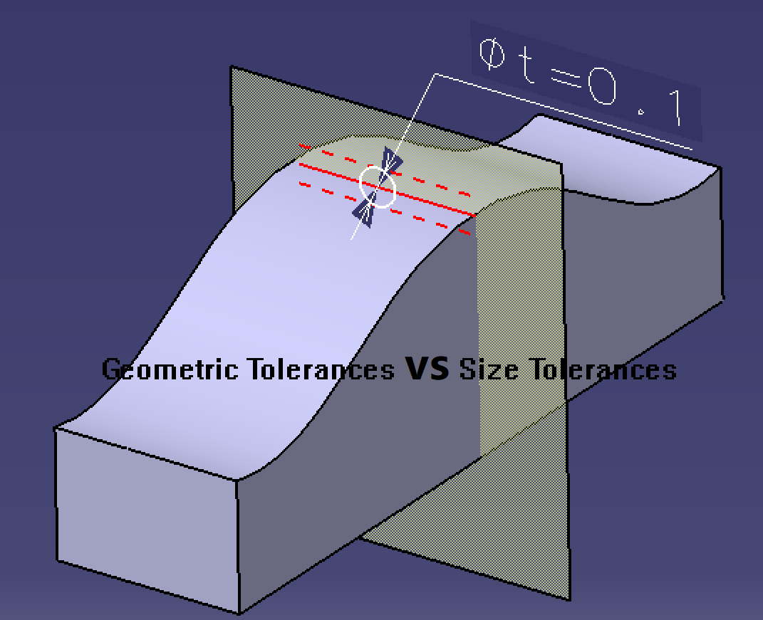
Are geometric tolerances important? How is it different from size tolerance? In this post, we’ll answer these questions.

Differences Between Geometric Tolerances & Size Tolerances
Geometric tolerances have an image that is difficult to grasp, so it seems difficult to understand. However, if you make good use of geometric tolerances, you will be able to draw good drawings without mistakes and prevent problems with transmission to the processor. In this article, we will explain the basics of geometric tolerances and why you should acquire them. If you are a design beginner who wants to learn geometric tolerances, please read on.
What Is Geometric Tolerance?
“Geometric tolerance” is a tolerance that regulates loss of shape (deviation of shaft bending and hole position), and is often contrasted with size tolerance (dimensional tolerance).
There will always be variations in the parts being machined, and to indicate the tolerance for that variation, the designer may indicate the size tolerance in the drawing.
However, since parts have geometric characteristics (shape, positional relationship, size, etc.) as well as size, size tolerances alone are not enough to convey design intent.
Geometric tolerances are useful in such cases, and can dictate intentions to the drawing that size tolerances cannot convey.
2. What Is The Difference Between Geometric Tolerance and Size Tolerance?
Here, we will explain the different parts of geometric tolerance and size tolerance in detail.
(1) Differences in the subject of regulation
Since geometric tolerances and size tolerances are subject to different regulations, size tolerances may not communicate design intent well.
For example, when you need a straight axis with as few bends as possible, regulating the size does not guarantee that it will be machined to the intended shape. This is because the size is a two-point measurement, and if the distance between the two points is within the tolerance, it will pass.
However, with geometric tolerances, it is possible to regulate the straightness of the axis as described above.
(2) Differences in tolerance ranges
Geometric tolerances and size tolerances also differ in “tolerance zones”. There are only two main types of tolerance zones: length and angle, but there are many tolerance zones for geometric tolerances.
(3) Differences in measurement methods
Two-point measurement using vernier calipers is the basic method for measuring size tolerances. On the other hand, when measuring geometric tolerances, dial gauges and 3D measuring instruments are used. This is because it cannot be measured by a two-point measurement.
For example, as shown in Fig. 4, put the shaft on the V block and check the straightness of the shaft. If the axis is tilted, it cannot be measured properly, so it is necessary to adjust the height on the left and right using a micro jack. Then, by measuring the height at several points with a dial gauge, the straightness of the shaft can be determined from the difference between the maximum and minimum measured values. Accuracy increases as the number of measurement points increases, but work efficiency must also be considered.
(4) Presence of datum
Size tolerances do not have the concept of datums, but geometric tolerances do. The setting of this datum has a great impact on part quality and cost.
A “datum” is a reference (line or plane) used to regulate the tolerance zone when indicating geometric tolerance. It not only serves as a basis for processing in part manufacturing, but also serves as a basis for measurement in inspections, helping to clearly communicate design intent.
For those who want to know more about datums, please also see the related column “Learn how to graphically represent geometric tolerances! What are the types, characteristics, and symbols of geometric tolerances? What is a datum?” Learn how to draw datums and other related knowledge.